# Upgrading insulation to improve energy efficiency
Rising energy costs and increasing awareness of environmental impact have pushed thermal efficiency to the forefront of property improvement priorities. With approximately 14% of UK emissions originating from domestic energy consumption and only 12% of households achieving Energy Performance Certificate Band C, the urgency for effective insulation solutions has never been clearer. Modern insulation technology offers homeowners the opportunity to dramatically reduce heating bills while simultaneously cutting carbon emissions by hundreds of kilograms annually. The challenge lies not simply in adding insulation, but in selecting appropriate materials, implementing proven methodologies, and addressing the complex thermal dynamics that govern heat loss in buildings. From calculating U-values to navigating regulatory frameworks, upgrading insulation requires technical knowledge combined with practical implementation skills.
Assessing current thermal performance using U-Value calculations and infrared thermography
Before embarking on any insulation upgrade, you need to understand precisely where your property is losing heat and quantify the scale of thermal inefficiency. This diagnostic phase forms the foundation of cost-effective improvement strategies, preventing wasted investment in areas that deliver minimal returns. Professional thermal assessments combine multiple methodologies to create a comprehensive picture of building performance, identifying not just obvious deficiencies but also subtle thermal bridges and air leakage pathways that compromise overall efficiency.
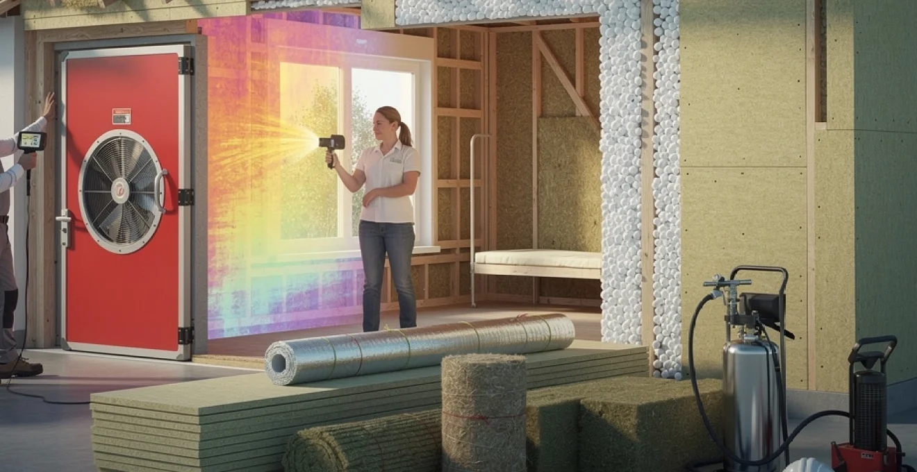
Conducting blower door tests to quantify air leakage rates
Blower door testing, also known as air pressure testing, measures the airtightness of your building envelope by creating a controlled pressure differential. A calibrated fan mounted in an external doorway depressurises the property to 50 Pascals below external air pressure, allowing technicians to measure the volume of air required to maintain this differential. Results are expressed in air changes per hour at 50 Pascals (ACH50) or air permeability in cubic metres per hour per square metre of envelope area at 50 Pascals (m³/h/m²@50Pa). Current Building Regulations require new builds to achieve 10 m³/h/m²@50Pa, though many older properties exceed 20 m³/h/m²@50Pa, indicating significant infiltration losses. During testing, thermal imaging cameras often identify specific leakage points around service penetrations, loft hatches, and window reveals, providing actionable data for targeted air-sealing interventions before insulation installation.
Interpreting thermal imaging results to identify cold bridges and heat loss pathways
Infrared thermography reveals temperature variations across building surfaces, highlighting areas where heat escapes preferentially. Professional thermographers typically conduct surveys during heating season with at least a 10°C temperature differential between interior and exterior environments. The resulting thermal images display warmer areas in red-orange spectrum and cooler areas in blue-purple, creating an intuitive visual representation of thermal performance. Cold bridges—structural elements that conduct heat more readily than surrounding materials—appear as distinct thermal anomalies, commonly occurring at wall-floor junctions, around window and door frames, and where internal walls meet external envelopes. Quantitative thermography assigns temperature values to each pixel, allowing calculation of surface U-values and identification of insulation voids within cavity walls. These surveys frequently reveal installation defects invisible through visual inspection, including compressed insulation batts, gaps in coverage, and moisture infiltration that compromises thermal resistance.
Calculating existing R-Values for cavity walls, lofts, and solid wall constructions
R-values (thermal resistance) and U-values (thermal transmittance) provide standardised metrics for comparing insulation performance. The relationship is reciprocal: U-value equals 1 divided by total R-value, with lower U-values indicating superior insulation. A typical uninsulated cavity wall constructed from 105mm brick outer leaf, 50mm cavity, and 100mm dense concrete block inner leaf achieves approximately U=1.5 W/m²K. Adding 100mm of cavity wall insulation with thermal conductivity (λ) of 0.035 W/mK contributes an R-value of 2.86 m²K/W, reducing the wall U-value to approximately 0.35 W/m²K—a 77% improvement in thermal performance. For loft spaces, 270mm of mineral wool
can deliver a combined R-value in excess of 6.0 m²K/W, bringing the resulting U-value down towards 0.16 W/m²K, in line with current new-build standards. Solid wall constructions, such as 225mm solid brick, typically exhibit U-values around 2.0 W/m²K when uninsulated, which is why internal or external wall insulation can be so transformative for energy efficiency. By calculating existing R-values for walls, roofs, and floors, you can prioritise upgrades where the gap between current performance and best practice is greatest, maximising return on investment. Many energy assessors use Standard Assessment Procedure (SAP) software to model these improvements and estimate potential reductions in annual space-heating demand.
Evaluating energy performance certificate ratings and SAP assessments
Energy Performance Certificates (EPCs) provide a high-level snapshot of your property’s energy efficiency, expressed as a rating from A (most efficient) to G (least efficient). While an EPC is not a substitute for a detailed thermal survey, it offers a useful starting point for identifying broad areas of improvement, particularly in relation to insulation thickness, glazing type, and heating system efficiency. The underlying SAP calculation estimates annual energy consumption, CO₂ emissions, and running costs based on a standardised occupancy profile, allowing you to compare different insulation upgrade scenarios. If your home currently sits in EPC Band D or below, targeted insulation improvements to lofts, cavity walls, or solid walls can often lift the property into Band C, unlocking access to certain government schemes and improving marketability. For more accurate planning, many homeowners commission updated SAP assessments after major retrofit works to verify performance gains and ensure compliance with evolving regulatory standards.
Selecting High-Performance insulation materials for retrofit applications
Once you understand where heat is being lost, the next step is selecting insulation materials that offer high thermal performance, durability, and compatibility with your building fabric. Not all insulation products are created equal: thermal conductivity, moisture behaviour, fire performance, and installation constraints all influence which solution is best suited to a specific application. You also need to consider practicalities such as available depth in cavities or rafters, the presence of services, and whether the property is occupied during works. Balancing these factors helps you avoid the common pitfall of choosing insulation based purely on headline U-values without accounting for buildability or long-term risk. By carefully matching products to context, you can create an energy efficient home that is warm, dry, and future-ready.
Comparing rigid PIR and PUR boards versus multifoil reflective systems
Rigid polyisocyanurate (PIR) and polyurethane (PUR) boards are widely used in retrofits because they deliver excellent thermal resistance in relatively thin build-ups. With typical thermal conductivities around 0.022–0.026 W/mK, products such as Celotex GA4000 or Kingspan Thermawall TW55 can achieve low U-values without sacrificing too much internal floor area, which is particularly valuable in small rooms or at rafter level. By contrast, multifoil reflective systems rely on multiple layers of low-emissivity foils separated by air pockets to reduce heat transfer through radiation and convection. These systems are lightweight and easy to handle, but their real-world performance depends heavily on correct installation with continuous air gaps and airtight detailing.
When comparing PIR boards to multifoils, you should look beyond marketing claims and focus on independently certified values under standard test conditions. In many cases, a combination approach works well: for example, using PIR between rafters and a thin multifoil layer internally to address thermal bridging and improve airtightness. Think of PIR as the dense insulating core and multifoil as the reflective jacket that fine-tunes performance. For homeowners aiming to maximise loft headroom or minimise disruption during internal wall upgrades, rigid boards usually offer the most predictable route to achieving stringent U-value targets, while multifoils can be a useful supplementary layer when space is extremely limited.
Natural insulation options: sheep’s wool, wood fibre, and hemp batts
For properties where moisture management, indoor air quality, or sustainability are priorities, natural insulation materials can be highly attractive. Sheep’s wool, wood fibre, and hemp batts typically offer thermal conductivities in the 0.037–0.045 W/mK range—slightly lower performance per millimetre than PIR, but with excellent hygroscopic properties. These materials can buffer humidity by absorbing and releasing moisture without losing significant insulation value, which makes them particularly suitable for traditional solid-wall buildings that need to “breathe”. In practice, they can help stabilise internal conditions and reduce the risk of interstitial condensation when paired with vapour-open finishes.
Natural insulations are also more forgiving to install, as they compress and friction-fit around irregular timbers and services, minimising gaps that would otherwise create cold spots. Sheep’s wool is often used between rafters and in stud walls, while wood fibre boards can be applied internally or externally as part of a vapour-permeable wall system. Hemp batts, with their combination of thermal and acoustic performance, are popular for refurbishments where sound insulation is also a concern. If you are retrofitting a listed building or heritage property, specifying vapour-permeable natural insulation alongside lime-based plasters and renders can be an effective way to improve energy efficiency without trapping moisture in the original fabric.
Spray foam solutions: Open-Cell versus Closed-Cell polyurethane applications
Spray foam insulation offers the ability to create a continuous, gap-free layer that conforms to complex shapes and penetrations, making it attractive for lofts, roofs, and difficult-to-reach voids. Open-cell polyurethane foams are relatively low density, with a spongy texture that allows vapour diffusion while providing good acoustic absorption and moderate thermal performance (λ around 0.034–0.039 W/mK). Closed-cell foams are denser, more rigid, and deliver higher R-values per inch (λ around 0.024–0.028 W/mK), as well as acting as an effective air and vapour barrier. This difference in structure is crucial when deciding which type to use in a given situation.
However, spray foam is not without controversy in retrofit applications, particularly in domestic roofs. Poorly designed or incorrectly installed spray foam can trap moisture against timbers, potentially accelerating rot and complicating future maintenance. It may also affect mortgageability if lenders are cautious about unknown long-term risks. If you are considering spray foam, it is essential to work with installers who follow manufacturer guidance, provide third-party certification, and design the system with proper ventilation and moisture control. Treat spray foam as a specialist solution best reserved for specific problems—such as hard-to-access rafter voids or curved roofs—rather than a universal answer to home insulation.
Aerogel blanket technology for Space-Constrained insulation upgrades
Aerogel blanket insulation represents the cutting edge of high-performance retrofit technology, combining extremely low thermal conductivity (as low as 0.014–0.018 W/mK) with minimal thickness. Originally developed for aerospace applications, aerogel blankets consist of a silica-based matrix embedded within a fibrous carrier, creating a highly porous material that dramatically slows heat transfer. In practical terms, this means you can achieve comparable thermal resistance to standard mineral wool or PIR using a fraction of the thickness—ideal for tight spaces such as window reveals, junctions, or internally insulated walls where every millimetre counts.
Because aerogel products are significantly more expensive than conventional insulations, they are usually deployed strategically rather than across whole surfaces. For example, you might use mineral wool or PIR for the bulk of a wall or roof and then add aerogel around structural penetrations, lintels, or party wall junctions to reduce thermal bridging. Think of aerogel as the precision tool in your insulation toolkit: you use it where conventional materials cannot physically fit yet you still need to meet stringent U-value or condensation risk criteria. When installed correctly as part of a well-detailed system, aerogel blankets can help older properties reach modern energy performance standards without excessive loss of internal space.
Loft and roof space insulation techniques for maximum thermal resistance
The roof is typically one of the largest sources of heat loss in an uninsulated property, with up to 25% of heat escaping through the loft in some homes. Upgrading loft and roof insulation is therefore one of the most cost-effective measures you can take to improve energy efficiency. Whether you have a simple cold roof with a horizontal ceiling joist layout or a complex room-in-roof configuration, there are proven methods to enhance thermal performance while preserving ventilation and managing moisture. The key is to choose the right build-up—at ceiling level, rafter level, or a combination—so that you achieve both comfort and compliance without creating condensation problems.
Installing 270mm mineral wool between and over ceiling joists
For traditional cold lofts where the loft space itself is unheated, laying mineral wool insulation at ceiling level remains the most straightforward and economical solution. Current best practice in the UK is to install a total thickness of around 270–300mm of mineral wool, typically in two layers: one between the ceiling joists and a second cross-laid over the top to minimise thermal bridging through the timbers. With a thermal conductivity of about 0.044 W/mK, this build-up can achieve U-values close to 0.16 W/m²K, significantly reducing heat loss compared to the 100mm or less found in many older homes. You can often carry out this work yourself, provided you take appropriate safety precautions and avoid compressing the insulation under stored items.
To maintain functionality, you may want to create raised storage platforms using loft legs or timber battens that sit above the full insulation depth. This prevents squashing the mineral wool, which would reduce its thermal resistance, much like flattening a thick duvet. It is also important to ensure that any downlighter fittings are either rated for direct contact with insulation or protected with suitable fire-rated covers to maintain airflow and safety. Loft hatches, pipes, and tanks should be insulated and draught-sealed to avoid becoming cold spots that undermine overall performance. By paying attention to these details, you can turn a basic loft insulation upgrade into a high-performing thermal barrier that will keep paying back for decades.
Rafter-level insulation using kingspan kooltherm K7 or celotex GA4000
Where the loft is used for storage, services, or future conversion—or where you simply want a warmer, more usable space—insulating at rafter level can be more appropriate than insulating at ceiling level. High-performance rigid boards such as Kingspan Kooltherm K7 or Celotex GA4000 can be fitted between and below rafters to create a warm roof, maintaining the loft within the insulated envelope. Because rafters are often only 100–150mm deep, you may need to combine partially between-rafter boards with an additional layer fixed underneath, creating a continuous insulated layer that reduces thermal bridging through the timber. With careful detailing, rafter-level systems can achieve U-values in the region of 0.13–0.18 W/m²K, even in older roofs.
Installing rigid boards at rafter level requires precise cutting and fitting to avoid gaps, as even small voids can act like open windows in an otherwise well-sealed jacket. You should also incorporate a suitable vapour control layer (VCL) on the warm side of the insulation to limit the amount of moisture-laden air entering the roof build-up. In many proprietary systems, the VCL is integrated into foil-faced boards or separate membranes taped at joints to create a continuous barrier. Because rafter-level insulation alters the hygrothermal behaviour of the roof, it is advisable to seek professional design input and, where necessary, Building Control approval, particularly if you are changing the roof covering or altering structural elements.
Addressing ventilation requirements and preventing condensation in cold roofs
One of the most common mistakes in roof insulation upgrades is ignoring ventilation and condensation control. In a cold roof configuration, where insulation sits at ceiling level and the loft above remains unheated, the space above the insulation must be ventilated to the outside to remove moisture that migrates through the ceiling. Without adequate ventilation, warm moist air can condense on cold roof timbers and underfelt, leading to mould growth and timber decay. Standard guidance typically calls for continuous eaves ventilation and, in some cases, high-level vents or ridge ventilation to ensure cross-flow of air across the roof void.
When you add or increase loft insulation, you should take care not to block existing ventilation paths at the eaves. Ventilation baffles or trays can be installed to keep insulation clear of the roof felt while maintaining a clear airflow path from soffit vents into the loft. Think of this as giving your roof space a way to “breathe out” moisture, just as you would crack a window in a steamy bathroom. In properties where external ventilation is limited or where the roof design is complex, mechanical ventilation with heat recovery (MVHR) or passive stack systems can help control humidity at the whole-house level, indirectly reducing condensation risk in the loft.
Room-in-roof conversions: combining rigid boards with breathable membranes
Room-in-roof or loft conversions present particular challenges because the sloping ceilings, dwarf walls, and dormer cheeks all form part of the thermal envelope. To achieve a comfortable, energy efficient room, you often need a layered approach: high-performance rigid boards between and below rafters, insulated studwork to dwarf walls, and careful treatment of junctions around dormer windows and steel beams. Breathable roof membranes on the cold side of the insulation allow water vapour to escape while preventing wind-driven rain ingress, reducing the need for traditional cross-ventilation in some warm roof systems when combined with appropriate detailing.
Because space is at a premium in attic rooms, specifying products with high R-values per millimetre—such as PIR or phenolic boards—is usually essential to meet modern U-value targets without sacrificing headroom. At the same time, you must maintain a continuous vapour control layer on the warm side of the insulation, taping and sealing around penetrations such as downlights and service routes. Any gaps at junctions between sloping ceilings, flat ceilings, and stud walls can become thermal weak points, leading to cold patches and potential condensation. A well-designed room-in-roof upgrade, however, can turn an underused attic into a warm, low-energy living space while significantly improving the overall energy performance of the property.
Cavity wall and external wall insulation installation methodologies
Wall insulation upgrades can transform the thermal performance of a building, as walls typically account for a large proportion of heat loss in many UK homes. For properties with existing cavities, retrofit cavity wall insulation is often the quickest and least disruptive intervention, while solid wall homes may benefit more from external wall insulation (EWI) systems. Choosing between these approaches depends on construction type, exposure to wind-driven rain, planning constraints, and your tolerance for internal or external disruption. By following proven installation methodologies, you can avoid common pitfalls such as damp bridging, incomplete fill, or compromised detailing around openings.
Injecting EPS beads, mineral wool, or expanding foam into existing cavities
For post-1920s properties built with cavity walls, injecting insulation into the cavity can significantly improve energy efficiency with relatively modest cost and disruption. Expanded polystyrene (EPS) beads, blown mineral wool, and, less commonly, expanding foam are typical infill materials, each with distinct characteristics. EPS beads flow freely into cavities and can be bonded with a light adhesive to reduce settlement, offering good thermal performance and minimal moisture retention. Blown mineral wool provides a continuous insulating layer with good fire performance, though it may be more sensitive to water ingress in highly exposed locations if the outer leaf is defective.
The installation process involves drilling small holes in the external brickwork at regular intervals, then blowing the insulation material into the cavity under controlled pressure until it is fully filled. Reputable installers will carry out pre-installation checks to assess wall condition, exposure zone, and existing damp issues, as cavity insulation should not be added where driving rain penetration is already a problem. Post-installation, the drill holes are made good with colour-matched mortar, leaving the facade largely unchanged. When done correctly, cavity wall insulation can reduce wall U-values from around 1.5 W/m²K to 0.35–0.45 W/m²K, delivering noticeable improvements in comfort and heating bills.
External wall insulation systems: fixing phenolic boards with mechanical fixings and adhesive
For solid-wall properties or cavity walls that are unsuitable for internal insulation, external wall insulation provides a powerful way to improve thermal performance while also refreshing the building’s appearance. EWI systems typically involve fixing high-performance insulation boards—often phenolic, PIR, or EPS—directly to the external masonry using a combination of adhesive and mechanical fixings. Phenolic boards are popular in constrained locations because of their low thermal conductivity (around 0.021–0.024 W/mK), enabling slim build-ups to achieve U-values close to or below 0.3 W/m²K. The boards are staggered and tightly butted to minimise thermal bridging, with special detailing at corners, sills, and reveals.
Once the boards are fixed and any joints are sealed or meshed, the system is overcoated with a reinforced basecoat render, followed by a decorative finish coat. This creates a continuous insulated envelope that can significantly reduce cold bridging at floor slabs and internal partitions compared to internal wall insulation approaches. However, EWI does change the external appearance and may require planning permission, particularly in conservation areas or for listed buildings. Services such as downpipes, satellite dishes, and external lights will need to be removed and refixed onto the new surface, and window sills and eaves may need to be extended to accommodate the added thickness. When planned and executed properly, EWI can both modernise the look of a property and deliver substantial energy savings.
Rendering techniques using weber pral M or K rend silicone finishes
The final render layer in an external wall insulation system not only provides weather protection but also defines the visual character of the building. Through-coloured monocouche renders such as Weber Pral M and silicone-based systems like K Rend are popular choices due to their durability, low maintenance, and wide range of colours and textures. Weber Pral M, for instance, is a one-coat, cement-based render that can be scraped to a uniform finish, while K Rend silicone renders offer enhanced water repellence and resistance to algae growth, making them well suited to exposed or shaded elevations. Both can be applied over appropriate basecoat and mesh arrangements specified by the insulation system manufacturer.
From an energy efficiency perspective, the choice of render finish has less impact on U-value than the insulation thickness, but it does influence moisture behaviour and long-term performance. Silicone-based renders are often described as “water-shedding yet vapour-permeable”, allowing the wall to dry out while resisting driven rain—an important consideration for older masonry. Colour choice can also have a subtle effect on thermal dynamics: lighter colours reflect more solar radiation, reducing summer overheating risk, while darker tones absorb more heat. By combining a robust insulation build-up with a high-quality render finish, you can create an external envelope that is both thermally efficient and resilient to the UK’s varied climate.
Internal wall insulation strategies for solid wall properties and listed buildings
Where external wall insulation is impractical—due to planning restrictions, heritage value, or boundary constraints—internal wall insulation (IWI) offers an alternative route to improved thermal performance. IWI involves adding insulation to the inner face of external walls, usually in the form of insulated plasterboard, timber or metal stud systems filled with batts, or vapour-permeable boards in traditional buildings. The main challenge is to increase thermal resistance without introducing moisture problems or excessive loss of internal space. Because IWI moves the dew point closer to the internal surface, careful design of vapour control and junctions is essential to prevent interstitial condensation and mould growth.
In modern properties, a common approach is to fix insulated plasterboard—combining PIR or phenolic insulation with a plasterboard facing—directly to masonry using adhesive dabs and mechanical fixings. This method is relatively fast and can achieve substantial U-value improvements, but it creates concealed voids that must be detailed to avoid air movement and cold bridging. An alternative is to construct a timber or metal stud lining, install mineral wool or natural insulation batts between studs, and finish with plasterboard, incorporating a continuous vapour control layer on the warm side. This build-up allows services to run within the stud zone and can offer better acoustic performance, though it typically occupies slightly more space.
Historic and listed buildings demand a more nuanced approach. Many traditional solid walls are built with lime mortar and vapour-permeable finishes that allow moisture to move and evaporate. Applying impermeable, foil-backed insulation directly to such walls can trap moisture and accelerate decay. Instead, vapour-open systems using wood fibre boards, cork, or insulating lime plasters are often specified, allowing the wall to continue to “breathe” while still improving thermal performance. These systems are usually paired with compatible lime-based internal finishes and may deliver more modest U-value reductions than fully sealed systems, but they strike a safer balance between energy efficiency and conservation. In all cases, junctions at floors, ceilings, and internal partitions must be carefully detailed to reduce thermal bridging and ensure continuity of insulation.
Addressing thermal bridging at junctions, reveals, and floor penetrations using accredited construction details
Even the best-performing insulation can be undermined if thermal bridges—areas where heat can bypass the main insulation layer—are not properly addressed. Common problem zones include window and door reveals, junctions between walls and floors, structural steel penetrations, and party wall connections. These linear bridges not only increase overall heat loss but can also create cold surfaces where condensation and mould are more likely to occur, particularly in corners or behind furniture. To mitigate this, designers and installers should refer to Accredited Construction Details (ACDs) or equivalent guidance, which provide tested junction details that minimise thermal bridging and air leakage.
Practical measures might include wrapping insulation around window and door openings using thin but high-performance materials such as aerogel blankets or phenolic boards, ensuring that the insulation line remains as continuous as possible. At floor-to-wall junctions, especially in suspended timber floors, perimeter insulation and airtightness measures can significantly reduce heat loss and draughts. Structural elements such as steel beams or balcony connections may require thermal break components to interrupt heat flow between internal and external elements. Think of these details as stitching on a high-quality jacket: even if the fabric is excellent, poorly finished seams will let the cold in.
During retrofit projects, it is particularly important to coordinate between trades so that airtightness layers, vapour control membranes, and insulation align at junctions rather than being cut or displaced by later works. Blower door testing and infrared thermography can be used at the end of the project to verify that thermal bridges have been effectively minimised and to identify any remaining weaknesses. By combining robust insulation strategies with well-designed junction details, you can ensure that your upgraded building envelope delivers its full potential in terms of comfort, reduced energy consumption, and long-term durability.